
Sensing for Science - Level 1
What is Arduino?
Is a company born of the Ivrea Interaction Design Institute, their goal was to provide
a pathway for non-engineers to have the ability to develop electrical devices. Users
of any skill can use Arduino.
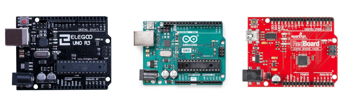
Arduino software and hardware is open sourced, meaning Arduino provides all their
code and schematics for anyone to use. Therefore, there are many Arduino clones available
to purchase.
There are many cool projects that can be done with Arduino: DIY 3D printers, heart
sensors, auto watering gardens, and many more.
Breadboards
Breadboards are a fast and easy way to prototype circuits with the ability to make
alterations and a low chance of damaging electric components. There are many types
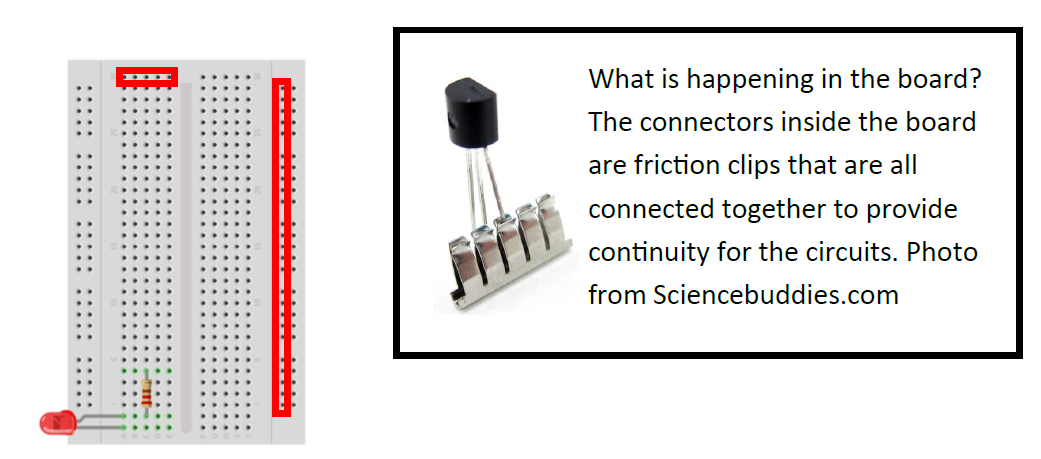
and sizes of breadboards. Our kits use a half-size breadboard that includes power
rails and component rails. All power rails are connected vertically and component
rails are connected horizontally in groups of 5 pins.
Breadboards get their name from the old style of prototyping circuits. To test cir-cuits
they used slabs of wood (like a cutting board) and used nails and solder to build
and test circuits before sending them off for manufacturing. It was a cheap method,
but time-consuming and not easy to make changes if needed.
What is happening in the board? The connectors inside the board are friction clips
that are all connected together to provide continuity for the circuits.
LEDs
LEDs or light emitting diodes are a semiconductor made from silicon when given the right amount of voltage will produce light. With too little voltage the LED does light up. With too much voltage the LED is ruined. LEDs light is directional meaning light is the brightest in one direction of the device. LEDs also have polarity, meaning they only allow electrons to flow in one direction. To make sure we have the polarity right we need to have the negative leg going to the negative side of the battery. The negative side can be identified in three ways: 1) the short leg side, 2) the flat edge of the bulb, and 3) the anvil (a larger piece of metal) inside the bulb.

Resistors
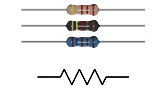
Resistors reduce the flow of electrons. They do not have polarity and come in all
shapes and sizes. The color bands tell us what the R-value of the resistor is. They
are very inefficient light bulbs, instead of making light, they dissipate energy by
heat. We will use them to help control the voltage in our LED circuit.
Ohm’s Law is foundational in dealing with electronics. The law describes the relationship
between voltage, current, and resistance. This relationship can be shown in this equation:
V=IxR. Check at the chart to see all the different ways to write out ohms law based
on what your knowns are. We can use Ohm’s Law to find a resistor value we need for
the LED circuit we will be using at this level. The LED I am using has a forward voltage
(the voltage required to work) of 3 volts with a current of .02 amps. Since we are
using the LED in series with the resistor the amperage will be the same. We will be
using a 5 volts power supply so the resistor needs to use up 2 volts. So we have two
knowns for the Ohm’s Law equation: V=2 volts and I = .02 amps. So now we use some
algebra to figure out the R (resistance) value of our resistor: 2 = .02 x R. For the
LED I am using I will need a 100-ohm resistor. Be sure to check the volt requirements
for your LED and find the resistor value you will need. It is common to use 100 to
300 ohms worth of resistance in a LED circuit. Most kits will have a 220 ohm resistor
for LED, you can use that.
First Circuit
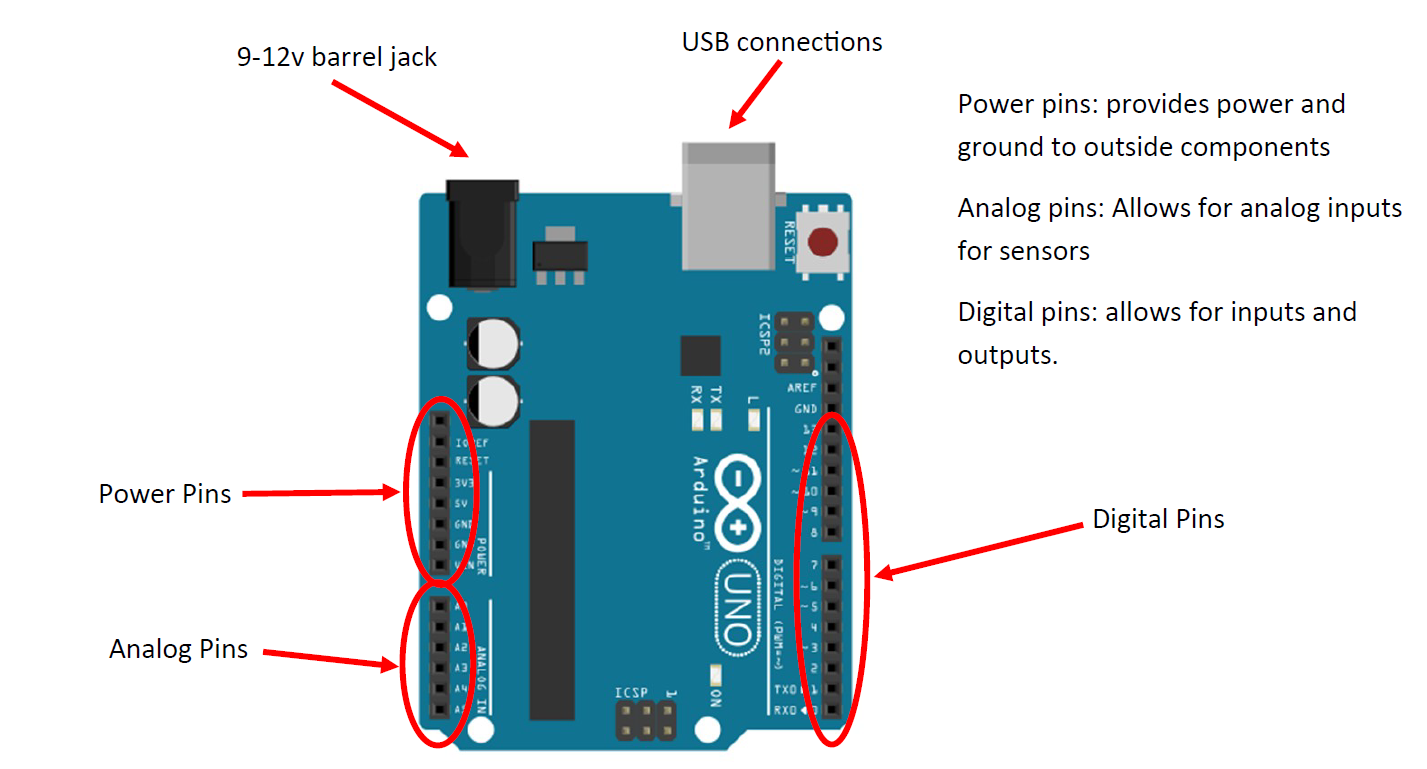
Let's build our first circuit. This circuit will make use of the information we learned so far and also test the power pins of the Arduino board. We will be using the following materials: Arduino board, Breadboard, USB cable, LED, 220-ohm resistor, and Jumper wires. Use the diagram and connection table to build the circuit. Test by connecting the USB cable to a pc and plugging it into the Arduino board.

Troubleshooting:
• My LED is not glowing but board is powered -> Check connections -> Check your polarity
-> Try another LED
• My Arduino board is not turning on or is beeping -> check for short circuits (power
to ground connecting) -> check cable -> check PC USB port -> try another board
The Arduino IDE
For us to start using the Arduino board more fully now we need to use the Arduino IDE (Integrated Development Environment). If you don’t have Arduino IDE on a computer yet go to www.Arduino.cc/downloads and follow the instructions on installation. It is free! There are other coding programs out there (some work better than others) but use them at your own risk.
Open the Arduino IDE and let's start coding. When you open Arduino and start a new document, you will see the “bare bones” code needed to work our Arduino. Let's break down each part.
Void setup
This section of code runs only once when the Arduino board is restarted (by a power-up or reset button). It is used for starting up any operation such as serial monitors, LCD screens, external modules, and pin settings. We are going to use this area to set up our digital pin 9 as an output. We do this by typing pinMode (9, OUTPUT); The semicolon is required when using this type of coding (C++). This tells the program end of the sentence and will give you an error if you forget.
Void loop
This section of code is considered the main code and is repeated over and over again. There are many things we can put into this section. We are going to use two commands for the next circuit digitalWrite and delay. The digitalWrite command is used to turn a digital pin HIGH (on) and LOW (off). The delay command is used to pause the program for several milliseconds. Remember to place your semicolons after each line. Copy the code to the right into your IDE. This will turn the LED on for 1 second and off for 1 second and repeat.

Verify
Now we should check our code to make sure it works. In the upper left-hand corner is the verify button. It will ask to you save your sketch (sketch is the name of the document) when you click it and then it will run through your code. If everything is correct you should see “compiling is complete” with no orange warnings. If something is wrong it will give you a warning in orange. Do not freak out, the error code might be overwhelming but practicing it can help you pinpoint your error (most likely you forgot a semicolon).
Construction
Once everything is good, let's build the circuit. Follow the circuit diagram.

Upload
It's time to upload! Plug your USB cable back into your Arduino and go to your code on Arduino IDE. At the top is the “Tools” menu. There is a board: area, check to make sure your board is selected here. Next is to go to the Port: and select the port your board is connected to, for windows it COM#. If you have multiple ports open try one and see if it works. Once your port is selected go back to the left-hand corner next to verify and click the upload. Your Arduino board should start blinking and you should see a loading bar in the IDE. If everything is working correctly you should get an “upload completed message” and your LED should start turning on and off. If not check the troubleshooting guide.
Troubleshooting:
• I got an COM error -> go back to your port options and try another port -> still
not working restart computer
• My LED is not on -> check your connections
• LED not blinking -> check code -> check connections
Congratulations! You completed the first level of this program. You can move on to
level 2 or play around with LEDs for a bit.
Want to explore more with the blink circuit?
• Trying changing the Delays
• Trying adding more LED controlled with the 9 pin
• Trying expanding the code and using multiple digital pins
• Try making a light show that goes to the beat of a song you like.
Sources:
- Arduino. (2018, February 5). What is Arduino? Retrieved July 8, 2022, from https://www.arduino.cc/en/Guide/Introduction/
Electrical4U. “Light Emitting Diode (LED): What Is It & How Does It Work? | Electrical4U.” Https://Www.electrical4u.com/, 28 Oct. 2020, www.electrical4u.com/led-or-light-emitting-diode/. - Science Buddies. (2019). How to Use a Breadboard. Science Buddies; Science Buddies. https://www.sciencebuddies.org/science-fair-projects/references/how-to-use-a-breadboard
- SparkFun Inventor’s Kit for Arduino. Vol. 4.0, SparkFun electronics, Inc., 2017.
Full code for the blink LED