Sensing for Science - Level 4 Data Loggers
Data loggers
We want to go out and collect data from the world. We could take our Arduino circuit
and a laptop out to collect data, but that gets challenging with all the equipment
and the fear of dropping your laptop. There is the current trend of using IoT (Internet
of Things) to send data via the internet, which works great when there is good internet.
Out here in Montana, internet connection is not guaranteed. So we will save data locally
but using a data logger SD card module. This device will allows us to save data to
a micro sd card for us to pull later.
This material is based upon work supported in part by the National Science Founda-tion
EPSCoR Cooperative Agreement OIA-1757351. Any opinions, findings, and conclu-sions
or recommendations expressed in this material are those of the author(s) and do not
necessarily reflect the views of the National Science Foundation.
Circuit #1
Let’s start with testing the module and the SD card. Wire up the following circuit
. CS->4, SCK->131, Mosi->11, Miso->12

Once you have the SD card module wired up, we can write some code to test the circuit.
Copy the code and upload it to the Arduino board. This code is also under examples
in the SD card library.
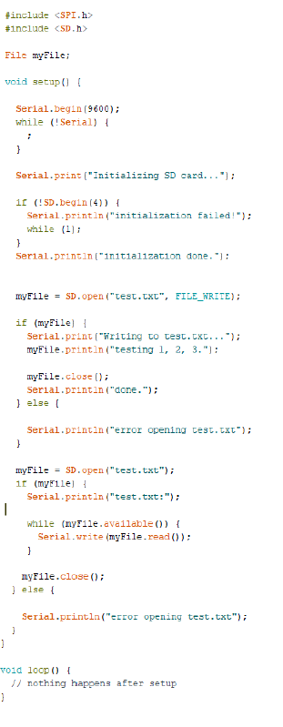
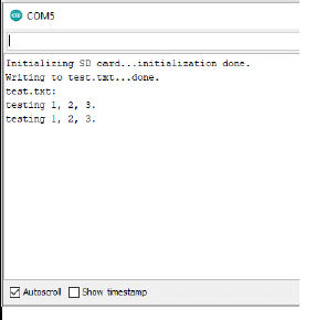
Upload the code to the Arduino board and open the serial monitor. If everything is
working correctly, you should see the results shown below. If you get an error message
you might have to reformate your SD card (see formatting steps in the instruction
video) or your SD card is damaged.
If you have an successful test you should be able to pull the SD card and open the
file on the pc. It will should up as a .txt file.
Circuit #2
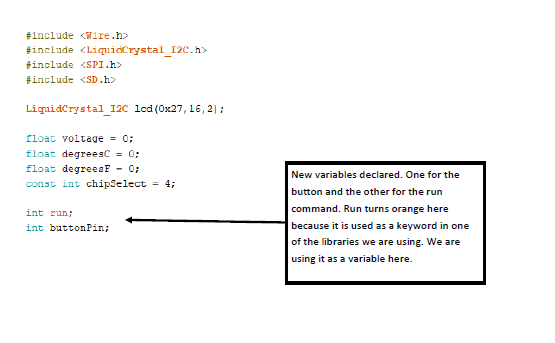
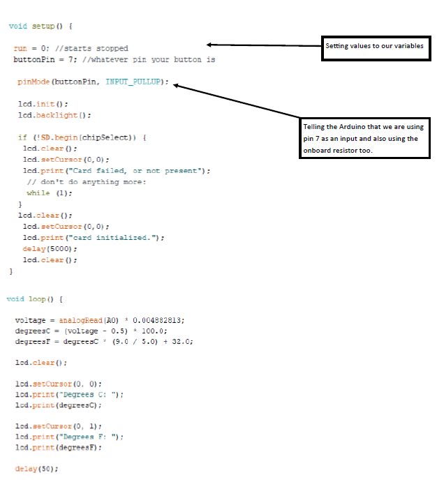
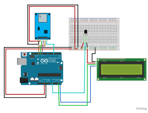
This next circuit we are going to build will collect temperature data for us at a
set interval of time (roughly 10 seconds). This circuit is great when you need to
step away but need continuous data collection. You will need a the TMP36, LCD (with
I2C), and the data logger. Most of the circuit you will recognize as it is the same
temperature sensor from the previous level.
Once you have the circuit built, we can move onto the code. You will notice that the
code is starting to get pretty complex. I will break down sections of the code that
are new to this project.
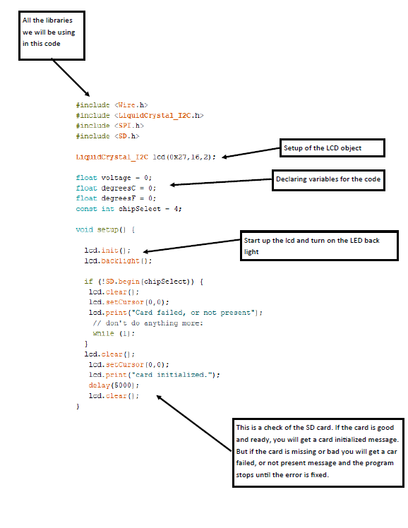
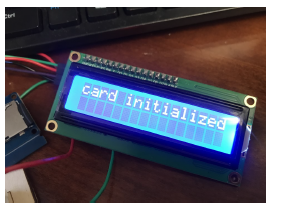
When you have the code ready and uploaded, the circuit will start working right away.
You should see the circuit go through its setup code. If everything is ready you should
see something like in the image below.
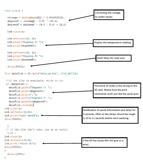
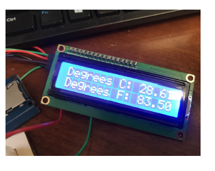
After the setup, the circuit will take a temperature reading and will display on the
LCD.
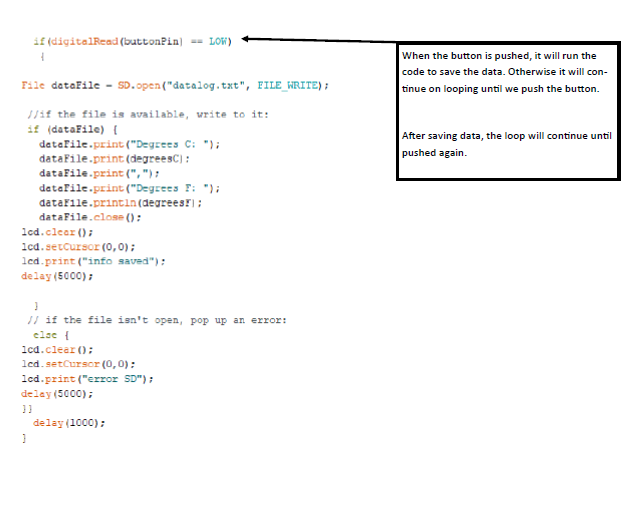
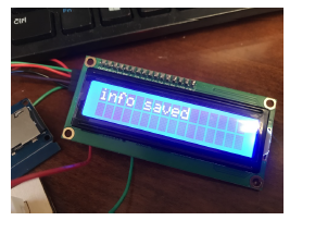
The circuit will save the data to a SD card and you will get a messaging them us that
the information was successfully saved.
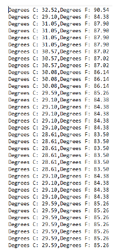
After we wait for awhile we can turn off the circuit and pull the SD card. Using a
SD card we can plug in the pc and open up the drive. You should see a data log file
as .txt file. We can open it and see our data.
Here is an example of the code in the notepad app. You can import this info into excel
to better analyze the date.
What are some down falls of the code we created? How can we improve this code to get
us more reliable data?
Circuit #3
Now that we have creating a data logger, lets create a circuit that will only collect
data when we want it to by pushing a button. We can keep everything from the previous
circuit connected. We will just add the button to the design.
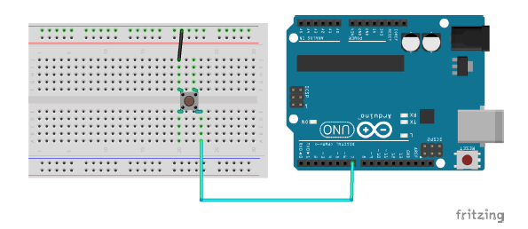
This setup will make the Arduino sense a button push. When the button is not being
pushed it sits in the “HIGH” status. When pushed current runs through the onboard
resistor and sets the status as “LOW”. We will use that to trigger the saving of our
data. Here is the new code for our circuit.