
Sensing for Science - Level 5 GPS
GPS modules
GPS modules are devices available to us that includes a GPS antenna and receiver.
This device is able to receive data from the GPS satellites and calculate the current
location of the module. The GPS module is then send us NEMA data to our Arduino board.
We will be using the Beitina Bk-180 GPS. This is a small yet accurate module. It is very easy to hook up and run on our Arduino boards.
The hook up for our GPS module is very simple. The VCC connects to 5v on the Arduino. TX connects to pin 6 on the Arduino. RX will go to pin 5 on the Arduino. GND will go to GND on the Arduino.

Once the circuit is built, it is time to test it. The code we are using is simple
and will use a new prebuilt library called SoftwareSerial.
This library allows us to create new serial ports using pins. Since we will need the
serial port to read the data, being able to create another port to read the GPS is
essential.
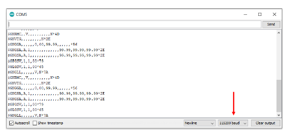
Upload the code and open the serial monitor. Change the baud rate to 115200 and watch
the data come in. You might get trash at first, but after a while if you have sight
to satellites will get useful data. Buildings and trees can block satellites. The
lines of code you are seeing in the monitor is the NEMA data.
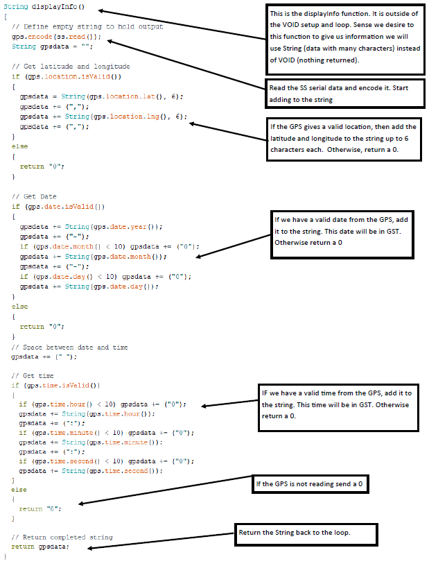
Now that we know the GPS module works, lets turn the NEMA data into something we can
easily understand. We are going to use a custom made library that is not available
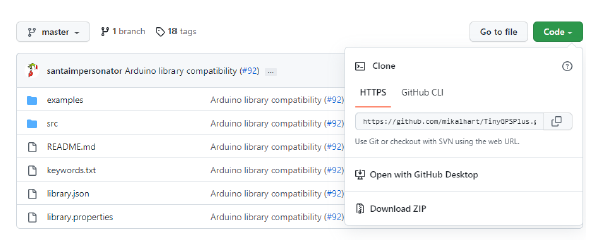
for install via the Arduino library. The library we need can be found here at the
following link: https://github.com/mikalhart/TinyGPSPlus. On the webpage is a green code button. Click it and click “download ZIP”.
When the download is finished, open Arduino and go to sketch->include library->import
library.
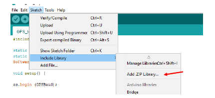
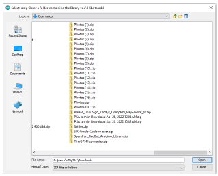
Find the downloaded zip file and open it. The TinyGPSPlus library is now available
for us to use in our code.
We are now ready for start writing the code.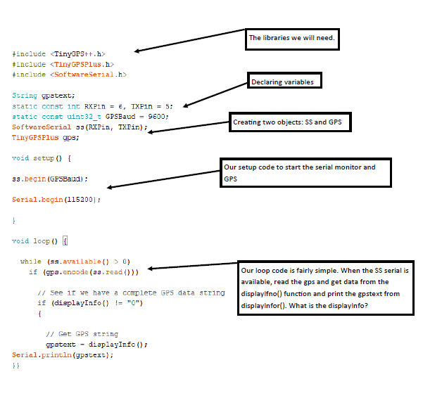
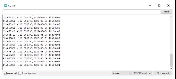
Lets upload the code and see if it works. When the upload is complete open the serial
monitor and see what the data looks like. It might take a moment for data to start
coming in. If after a while you still not getting a location try moving outside (laptops
make this easy). This data can be copied to the notepad and saved. If you import this
data into excel or google maps you can see how accurate the module is.
Sources:
Building a GPS System - SparkFun Electronics. (n.d.). Www.sparkfun.com. https://www.sparkfun.com/gps
Workshop, DroneBot. “Using GPS Modules with Arduino & Raspberry Pi.” DroneBot Workshop,
26 June 2021, dronebotwork-shop.com/using-gps-modules/. Accessed 5 Aug. 2022.